

Last Updated: November 8, 2026
Quick Summary
To connect model railway point motors and switches, match the switch to the motor type: use a momentary switch for solenoid motors and a latching or DPDT switch for slow-action motors. Wire the supply to the switch common, run each throw contact to the motor, then test each point before wiring the next.
- Solenoid motors need a brief pulse, so fit a momentary switch or capacitor discharge unit.
- Never wire a latching switch to a solenoid motor without a CDU, as the coil will overheat.
- A DPDT switch is the standard choice for reversing polarity to a slow-action motor.
- Test each point on its own before connecting the whole control panel.
- If a slow-action point moves the wrong way, swap the two motor supply wires.
Table of Contents
- Step 1: Choose the Right Point Motor for Your Layout
- Step 2: Plan Your Model Railway Point Motor Wiring Diagram
- Step 3: How to Wire a Point Motor to a Toggle Switch
- Step 4: DCC Point Motor Decoder Wiring
- Step 5: Test and Troubleshoot Your Installation
- Step 6: Model Railway Point Motor Troubleshooting
- Step 7: Get the Right Parts and Help from HobbyTrax
- Frequently Asked Questions
Step 1: Choose the Right Point Motor for Your Layout
Point motors are small electric actuators that move the blades of a turnout so trains can change tracks without you reaching in by hand.
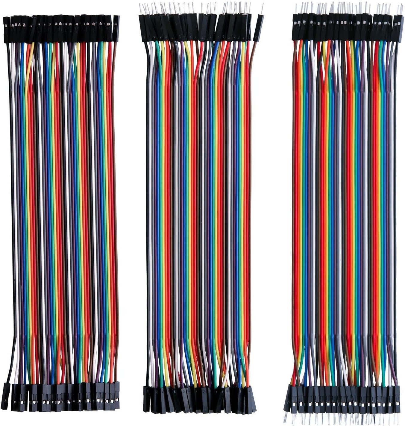
This guide walks you through the full job, from choosing a motor to testing the finished circuit.
Most beginners buy a motor first and plan the wiring later. That order causes trouble. Decide the motor type, then draw the circuit, then fit.
Solenoid vs Slow-Action Motors
Solenoid motors fire the point with a short burst of power. A coil pulls an operating pin across, and the blades snap to the new position.
Slow-action motors drive the point over a second or two. They are gentler on the blades and quieter in operation. Many use a servo, and some include built-in accessory switches for frog polarity.
A common mistake is mixing the two on one control panel without labelling which switch does what. Keep solenoid and slow-action controls separate so you never send a pulse to a servo.
Scale and Turnout Considerations
Motor choice depends on your scale and turnout. In OO gauge, solenoid motors are widely used and easy to mount under the board. Smaller scales leave less room beneath the turnout, so check the motor's physical size before you buy.
Also check the drive arm and operating pin line up with the tie bar on your turnout. A motor that does not align will strain the blades.
Step 2: Plan Your Model Railway Point Motor Wiring Diagram
A model railway point motor wiring diagram is a simple drawing that maps every wire from the power supply, through the switch, to the motor. Sketch it before you cut a single wire.
Good planning saves hours of fault-finding later. Here is what to include:
- The power source and its voltage
- The switch type and its terminal numbers
- The motor and its coil or drive terminals
- A capacitor discharge unit if you plan to use one
- Any frog polarity or indicator wiring
Mark which terminal is common and which are the throw contacts. Label each wire with a colour and stick to that colour scheme across the whole layout.
If you are mounting solenoid motors under the board, an under-baseboard mounting base for Peco and Hornby solenoid motors makes alignment easier and keeps the motor square to the turnout.

Step 3: How to Wire a Point Motor to a Toggle Switch
Wiring a point motor to a toggle switch comes down to three connections: common to the supply, and each throw contact to one side of the motor coil. But the switch you choose matters as much as the wiring, because a switch that suits a solenoid motor will damage or confuse a slow-action motor. This section is the switch-selection guide most wiring pages skip.
Match the switch to the motor type
| Switch type | Behaviour | Suits | Avoid with |
|---|---|---|---|
| Momentary toggle (spring-return to centre) | Sends a brief pulse only while held | Solenoid motors, especially with a capacitor discharge unit | Slow-action motors that need a sustained command |
| Latching toggle (stays where set) | Holds the contact continuously | Slow-action motors with their own end-stop control | Solenoid motors, because the coil stays energised |
| Centre-off toggle (three-position, stays off in the middle) | Off in the centre, latched each side | Slow-action motors where you want a neutral position | Solenoid motors unless paired with a CDU and brief operation |
| DPDT toggle | Two poles, each with two throws | Reversing polarity for slow-action motors, or cross-wired routes | Solenoid motors wired without a CDU |
| Push-button (momentary) | Pulse only while pressed | Solenoid motors on a simple panel | Any motor needing a held command |
A centre-biased momentary toggle switch suits pulse control of solenoid motors well. A latching or centre-off switch suits a slow-action motor that expects a steady command. A DPDT switch is the standard choice when you need to reverse polarity to a slow-action motor, because each pole feeds one side of the motor and the cross-wiring swaps positive and negative.
Watch out: never wire a latching switch to a solenoid motor without a capacitor discharge unit, because the coil will stay energised and overheat.
Wire a momentary switch to a solenoid motor
- Isolate all power before you start.
- Identify the common terminal on your switch.
- Run the supply to the switch common.
- Run each throw contact to the motor coil terminals.
- Run the motor return to the supply.
- Check every joint before applying power.
Wire a DPDT switch to a slow-action motor
- Isolate all power.
- Identify the two poles and their throws on the DPDT switch.
- Run the supply to both pole commons.
- Cross-wire the throws so each pole's output swaps polarity when the switch is thrown.
- Run the two outputs to the motor's two supply terminals.
- Test the direction and swap the motor wires if the point moves the wrong way.
For readers who want the full depth on crossovers and route setting, our helpsheet on wiring solenoid point motors covers indicators and frog switching too.


Using a Capacitor Discharge Unit
A capacitor discharge unit stores energy and releases it as a strong short pulse. That pulse throws the solenoid cleanly without holding current through the coil for long.
Our Tyson capacitor discharge unit for solenoid point motors takes a 16-24V AC or DC input and connects by screw terminals. Wire it between the supply and the switches, and check the included instructions before connecting.

Watch out: never leave a solenoid motor energised for long. A sustained feed overheats the coil, so use a momentary switch or a CDU.
Step 4: DCC Point Motor Decoder Wiring
DCC point motor decoder wiring lets you throw points from your throttle or a route command instead of a panel switch. The decoder takes commands from the track bus and fires the motor for you.
Connection basics:
- Feed the decoder from the DCC track bus
- Connect the motor to the decoder's output terminals
- Set the accessory address to match your plan
- Test one point before wiring the next
Check that your decoder suits your motor type. A solenoid decoder and a servo decoder are not interchangeable. Follow the decoder's own instructions for wire colours and terminal numbers, and never assume two brands wire the same way.
Step 5: Test and Troubleshoot Your Installation
Test each point on its own before you connect the whole panel. Apply power briefly and watch the blades move fully across.
Use a multimeter to check continuity along each wire run. Long wire lengths add resistance, so test at the motor end, not just at the switch.
A quick checklist:
- Does the motor throw both ways?
- Do the blades sit tight against the stock rails?
- Is the frog polarity correct for the new route?
- Any loose terminal screws?
Fix one fault at a time. Changing several things at once hides the real cause.
Step 6: Model Railway Point Motor Troubleshooting
Model railway point motor troubleshooting usually comes down to a handful of causes, but guessing wastes time. Work through a fixed test sequence with a multimeter so you prove each part of the circuit in turn. This is the method most wiring pages leave out.
Test in this order
- Power supply. Set the multimeter to the correct DC or AC range and measure at the supply output. Confirm the voltage matches what the motor and any CDU expect. If it is low or absent, fix the supply before touching anything else.
- Continuity along each wire run. With power off, set the multimeter to continuity and check from the switch terminal to the motor terminal. Long wire runs add resistance, so test at the motor end, not just at the switch.
- Switch contacts. Operate the switch and confirm continuity appears on the correct throw terminal and disappears on the other. A switch that never closes a contact is a common cause of one-way operation.
- Polarity and direction. For slow-action motors, confirm the polarity swaps when the switch is thrown. If the point moves the wrong way, swap the two motor supply wires rather than rewiring the panel.
- Motor operation. Apply power briefly and watch the blades move fully across. If the motor buzzes but does not throw, suspect a weak supply or a misaligned drive arm before replacing the motor.
Symptom, cause and fix
| Problem | Likely cause | Fix |
|---|---|---|
| Motor buzzes but won't throw | Weak or wrong supply | Check supply voltage and current |
| Nothing happens | Broken wire or loose terminal | Test continuity with a multimeter |
| Point throws one way only | Faulty switch contact | Check throw terminals |
| Motor overheats | Sustained current | Fit a momentary switch or CDU |
| Blades don't fully move | Drive arm misaligned | Re-check mounting and pin alignment |
| Frog dead on one route | Frog polarity not switched | Check accessory contacts or relay |
A common mistake is assuming a dead motor when the real fault is a single loose terminal screw. Check connections before replacing parts.
Watch out: when testing a solenoid motor, keep each pulse brief. Holding power on to "see if it moves" is the quickest way to overheat a coil.
Accessory switches and frog polarity
Many point motors include, or can be fitted with, accessory contacts that change over when the point throws. These can switch frog polarity, operate a signal or light an indicator on the panel. If your motor has no accessory contacts, a separate relay or a microswitch linked to the tie bar can do the same job. Check the motor's instructions for the contact rating before connecting anything, because a frog feed and a signal may draw more current than the contacts are rated for.
Step 7: Get the Right Parts and Help from HobbyTrax
The right parts make this job far easier. HobbyTrax stocks switches, capacitor discharge units and helpsheets for solenoid point motors.
Start with a clear diagram, use momentary switches for solenoids, and test each point before moving on. That routine catches most faults early.
If you are unsure what suits your layout, check compatibility before you buy.
Connecting point motors and switches rewards patience more than speed. Draw the circuit, wire one point at a time, and test as you go.
A note from HobbyTrax: This article reflects our practical modelling experience and information available at the time of writing.
Frequently Asked Questions
How do you connect a model railway point motor to a switch?
Connect the point motor's common wire to one terminal of a momentary toggle switch, then run the switch's other terminals to the power supply. For solenoid motors, use a centre-biased (ON)-OFF-(ON) switch so the pulse stops when you release it. Always test the motor before fitting it permanently under the board.
What type of switch do I need for a model railway point motor?
Solenoid point motors need a momentary switch, such as a centre-biased SPDT toggle, because they require a brief pulse of power. Slow-action motors use a standard DPDT switch to reverse polarity. Match the switch to your motor type and check the current rating before buying.
Can model railway point motors be powered by a DCC system?
Yes, but they need a DCC accessory decoder between the track bus and the motor. The decoder receives commands from your throttle and fires the motor. Wiring differs from DC control, so follow the decoder's instructions carefully and keep the motor's power supply separate from the track signal.
Why does my model railway point motor only move in one direction?
A motor that moves one way usually has a faulty switch contact, a reversed wire, or a capacitor discharge unit that is not recharging. Check the switch with a multimeter, confirm both coils receive power, and test the CDU output. Reversing the wires at the switch often solves it.
