

Table of Contents
- DCC Bus Wiring: Getting the Backbone Right
- Model Railway Track Feeders: How Often and Where
- DCC Power Districts: Splitting a Layout Safely
- Accessory and Programming Buses: Keeping Them Separate
- DCC Wiring Troubleshooting: Finding Shorts and Dead Sections
- Wire Management and Future Expansion
- Frequently Asked Questions
DCC Bus Wiring: Getting the Backbone Right
Advanced DCC wiring techniques guide the whole electrical health of a layout, and the bus is where that health starts. A DCC bus is the pair of heavy conductors running beneath the baseboard that carries the command station's signal and power to every section of track. Get the backbone right and everything downstream behaves; get it wrong and you spend weekends chasing mystery shorts. This guide from HobbyTrax walks through bus sizing, track feeders, power districts, and fault finding in practical terms.

Wire thickness, length and voltage drop
Voltage drop is the silent killer of reliable running. The longer and thinner the bus, the more the signal degrades between the command station and the far end of the layout. For most home layouts, a bus of heavier conductor than your droppers is the sensible starting point. The exact cross-section depends on your run length and expected current draw, so check the manufacturer's guidance and our Hobby Trax Helpsheet - DCC Bus wiring for a worked reference. If a locomotive stutters only at the far end of a long run, suspect the bus before you suspect the decoder.
Twisting the bus and separating it from track
Twisting the two bus conductors together helps cancel electrical noise and keeps the DCC signal cleaner over distance. Route the bus away from mains cabling and keep it clear of the track where practical. A common mistake is running the bus tight against a parallel track feed for metres on end; a little separation costs nothing and avoids headaches later.
Model Railway Track Feeders: How Often and Where
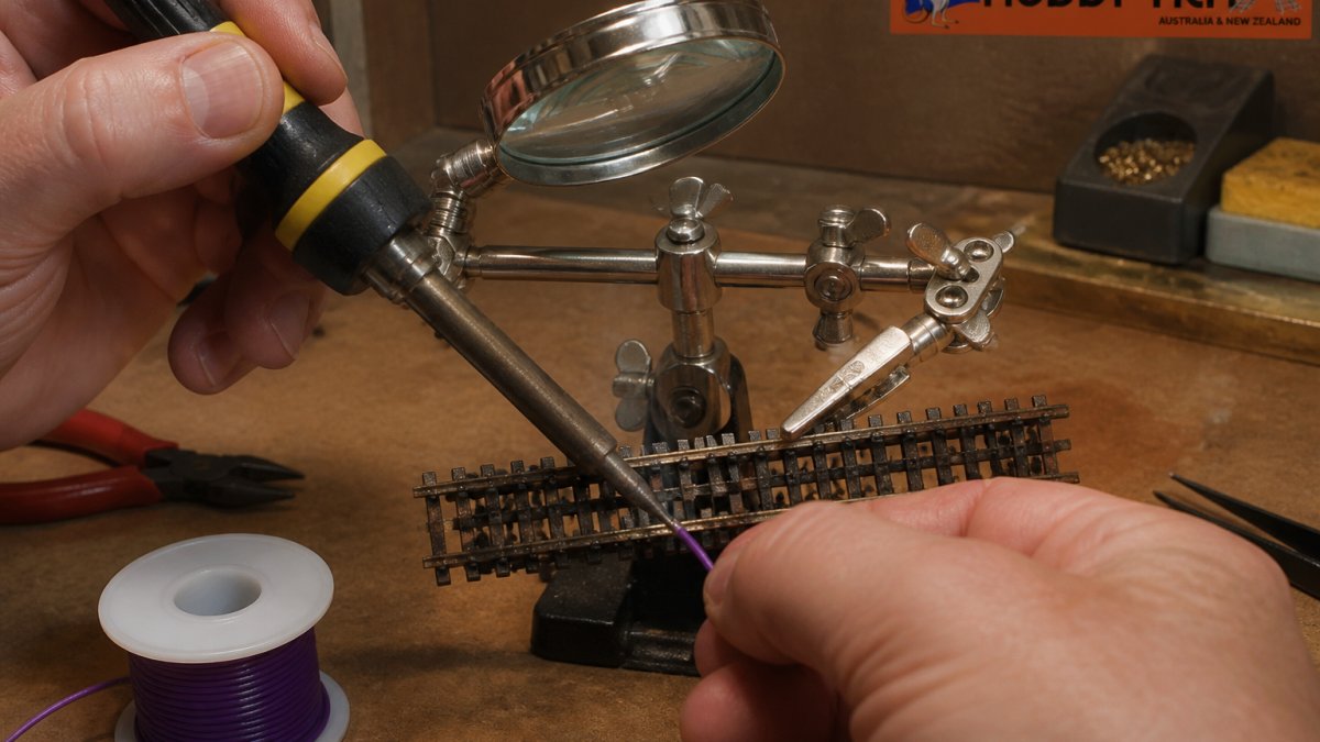
Model railway track feeders are the short dropper wires that connect the rails to the bus, and their spacing matters more than most beginners expect. As a rule, fit a feeder to every isolated section of rail rather than relying on rail joiners to carry current along. Rail joiners loosen, corrode, and create intermittent faults, so treat them as mechanical alignment, not as electrical conductors.
Dropper wire choice and soldering to rail
For droppers, thin flexible wire is easier to hide and solder. Our 7/0.1mm Ultra-Thin DCC Decoder Wire suits this job, being 0.6mm in diameter and rated to 0.5A maximum. Solder to the underside or outside web of the rail where it is least visible, keep the joint brief to avoid melting sleepers, and insulate anything that could touch a neighbouring rail. Disconnect power before soldering, and test each dropper with a meter before you bury it under scenery.

DCC Power Districts: Splitting a Layout Safely
DCC power districts divide a layout into separately protected electrical zones so a short in one area does not shut down the whole railway. Splitting a layout into districts is one of the highest-value advanced techniques, especially once your track length grows. A short in a goods yard then stops only that yard, while the main line keeps running.
Circuit breakers, boosters and where to draw the line
A circuit breaker protects a district by cutting power when current spikes. A booster adds power when a single command station cannot supply the whole layout. Draw the line between districts at natural boundaries such as station throats or section gaps, and match each district to the current it will realistically draw.
| District Type | What It Does | Best For | Watch Out For |
|---|---|---|---|
| Single bus | One circuit for the whole layout | Small layouts, one operator | Whole layout stops on any short |
| Breaker-protected district | Isolates a zone on fault | Medium to large layouts | Needs clean section gaps |
| Booster-fed district | Adds power to a zone | Very large layouts, multiple trains | Correct phasing between boosters |
Accessory and Programming Buses: Keeping Them Separate
Accessory and programming buses should stay electrically separate from the main track bus. Point motors, lighting, and stationary decoders draw current and generate noise that has no business sharing a feed with your running track. Keep a dedicated accessory bus for these loads, and keep the programming track isolated from the main line so you programme without affecting running locomotives.

Our Hydra 16-Channel DC/DCC Bus Bar with Isolation is designed for exactly this kind of organisation, with 16 output terminals, a 5A maximum per board, and an isolate function to switch off sections during fault finding. For controllers that lack dedicated programming terminals, a switchable programming track solves the problem neatly; the TCS LT-50 DCC Programming Track Switch is a plug-and-play option for the TCS LT-50.
DCC Wiring Troubleshooting: Finding Shorts and Dead Sections
DCC wiring troubleshooting is mostly a process of elimination, done methodically rather than by guesswork. A short trips the whole district; a dead section shows no power at all. The two need different approaches, so identify which you have before you start.
For a short, isolate the district using your breaker or bus bar isolate function, then reconnect sections one at a time until the fault reappears. For a dead section, check the dropper joint first, then the bus connection, then the rail gap. A multimeter is your best friend here.
Testing before you lay track permanently
Test every feeder, district, and accessory circuit before ballast and scenery go down. Run a locomotive across each section, check polarity, and confirm the programming track works in isolation. Once track is fixed and covered, corrections become far more disruptive.
Wire Management and Future Expansion
Wire management is what separates a layout that stays reliable for years from one that becomes a tangle of mystery faults. Group bus runs together, secure them with clips or conduit, and keep a written record of what connects where. Leave spare capacity in your bus and bus bars so a future siding or district does not mean rewiring the whole underside.
Hobby Trax Helpsheet - DCC Bus wiring →
We have seen too many otherwise excellent layouts undone by loose wiring. If you plan to expand, run a heavier bus now than you need today, and leave a few spare terminals on each board. Future you will be grateful.
Building a reliable DCC layout comes down to planning the backbone before the scenery, and that is where we can help. At HobbyTrax, we stock the wire, bus bars, and programming accessories to put a sound wiring plan into practice, and we are happy to talk through compatibility questions before you commit. Explore our DCC and electrical range, or send us a message about your layout and we will point you in the right direction.
This article was written with the best intentions and reflects personal views. Products and technology change constantly, and while we try our best to provide correct information, please verify specifications against the relevant manufacturer's documentation before purchasing or installing.
Frequently Asked Questions
How do you wire a DCC bus on a model railway?
Run two heavy-gauge wires, often called the bus, beneath the baseboard following the main track route. Connect your command station to one end, then attach short dropper wires from the rails down to the bus at regular intervals. Keep the bus runs as short as practical and use thicker wire for longer layouts to reduce voltage drop. A twisted pair helps reduce interference. Our free DCC bus wiring helpsheet covers wire thickness and routing in more detail.
How often should you add DCC track feeders?
A common approach is a feeder every 1.5 to 3 metres of track, with additional feeders after every set of points and at the start of any isolated section. Rail joiners can loosen over time, so relying on them for continuity is risky. More feeders mean more consistent running, especially on larger layouts. If a locomotive stutters on a particular stretch, that section probably needs another feeder.
What is the difference between a DCC bus wire and a track feeder?
The bus is the main pair of wires carrying power and the DCC signal around the layout. Feeders, sometimes called droppers, are the short wires that connect individual pieces of rail to that bus. The bus handles current distribution; the feeders deliver it to the track. Keeping these roles separate makes fault finding easier, because you can isolate a section without disturbing the whole run.
How do you divide a DCC layout into power districts?
Split the layout into logical blocks, such as separate boards, stations or yards, and give each its own feed from a circuit breaker or booster. Each district should be electrically isolated from the next using insulating rail joiners. This way a short in one area shuts down only that district, not the entire layout. The Hydra 16-channel bus bar, with its isolate function, is one way to organise and switch sections for fault finding.
How can you find a short circuit on a DCC layout?
Disconnect power first, then isolate sections one at a time until the short disappears. A bus bar with an isolate function speeds this up considerably. Check recent work first: a stray strand of wire, a reversed dropper or a wheel bridging a gap are common culprits. Once you find the section, inspect it visually and with a multimeter before restoring power.
Do DCC layouts need a separate bus for accessories?
It is good practice to run a separate accessory bus for point motors, signals and lighting, rather than tapping them off the track bus. Accessory loads can cause voltage fluctuations that affect running, and a fault on the accessory side will not then bring the whole layout down. Keep the two buses physically separated and clearly labelled.
How do you test DCC wiring before laying track permanently?
Before ballasting or fixing track down, connect the bus and feeders and run a test locomotive across every section. Check for smooth running, listen for unusual buzzing and feel for warm wires or connections. Use a multimeter to confirm continuity and check for shorts between the two bus wires. Fixing problems is far easier before the track is permanently fixed.
How do you wire turnouts for DCC?
Most turnouts work on DCC without modification, but the frog needs attention. Insulated frog turnouts are simplest; live frog turnouts need a switch or auto-reverser to change frog polarity with the blades. Feed the toe end and both departure roads so power continues whichever way the blades are set. Always check the manufacturer's instructions, as wiring varies between brands and turnout types.