

Table of Contents
- DC vs DCC Wiring: What's the Real Difference?
- DC vs DCC Comparison: Control, Wiring, Cost and Suitability
- Basic Components for DC and DCC Model Railway Wiring
- Wiring a Basic Two-Rail DC Layout (and Isolated Sections)
- DCC Wiring: Power Bus, Track Droppers and Wire Sizes
- Soldering Model Railway Track: When and Why It Beats Rail Joiners
- DCC Power District Management: Points, Frogs, Reverse Loops and Shorts
- Troubleshooting Common Model Railway Wiring Problems
- Your Beginner Wiring Checklist
- Frequently Asked Questions
Last Updated: September 28, 2026
DC vs DCC Wiring: What's the Real Difference?
A beginner guide to DCC wiring starts with one honest truth: the track is just two rails, and everything that makes trains move happens underneath the baseboard. At HobbyTrax, we talk to new modellers every week who are nervous about wiring, and the good news is that the underlying principles are simpler than they look. This guide covers model railway wiring from the ground up, starting with the one decision that shapes everything else: DC or DCC.
How Conventional DC Control Works
DC model train wiring feeds a variable voltage to the rails. Turn the throttle up, and the locomotive speeds up; turn it down, and it slows. Direction comes from reversing the polarity (positive and negative), so the loco follows whatever the controller tells the track.
The catch is that every train on the same electrical section moves together. To run two trains independently, you divide the layout into isolated sections and switch power between them. That is why traditional DC layouts have so many switches and wires: the wiring is the control system.
How DCC Changes the Wiring Game
DCC keeps a constant voltage on the rails and sends digital commands addressed to individual locomotives. Each loco carries a decoder (a computer chip) with its own address, so two trains can sit on the same piece of track and go in opposite directions.
Wiring becomes a distribution job rather than a switching job. You run a power bus under the layout and feed the track from it, and the commands travel through the rails to the decoders. Fewer switches, more trains.
DC vs DCC Comparison: Control, Wiring, Cost and Suitability
Factor |
DC (Analogue) |
DCC (Digital) |
|---|---|---|
Control method |
Variable voltage on the rails |
Constant voltage, digital commands |
Independent trains |
One per isolated section |
Many, each with its own address |
Wiring complexity |
High (section switches and cab control) |
Moderate (bus and droppers) |
Typical cost |
Lower entry cost |
Higher, as each loco needs a decoder |
Expansion |
Add sections and switches |
Add decoders and power districts |
Best for |
Small layouts, one or two trains |
Larger layouts, multiple trains, sound |
Neither system is "better". DC suits a compact shunting layout where one operator drives one train at a time. DCC earns its keep the moment you want two trains running while you shunt a third.
Basic Components for DC and DCC Model Railway Wiring
A DC layout needs a controller, two wires to the track, and insulated joiners plus switches wherever you create a section. Add a bus bar if you would rather not crowd a terminal block with every feed.

A DCC layout needs a command station, a power bus running beneath the baseboard, and a dropper from each rail section up to that bus. Decoders go inside the locomotives, and a stay-alive capacitor helps short-wheelbase locos keep running over dirty or dead track.
Wiring a Basic Two-Rail DC Layout (and Isolated Sections)
Start with the simplest possible circuit: controller output to the rails, one wire per rail, nothing else. Test it with a single locomotive before you add anything.
To run a second train, cut one rail with an insulated rail joiner and feed that section through a switch. The switch chooses which controller feeds the section, which is how isolated track sections let two DC trains run on one layout.
- Run a two-wire feed from the controller to the track
- Test with one locomotive on a plain oval
- Mark where you want a second train to sit
- Fit insulated joiners on one rail at each end of that section
- Wire the section through a single-pole double-throw switch
- Check both controllers work the section independently
Get this working, and you understand DC wiring. Everything after this is repetition.
Hobby Trax Helpsheet - DCC Bus wiring →
DCC Wiring: Power Bus, Track Droppers and Wire Sizes
The DCC bus wire is the backbone of the layout: two heavy conductors running under the baseboard, following the track plan. Track droppers are short feeds soldered to the rails and connected up to the bus every metre or so, or at least every second track section.

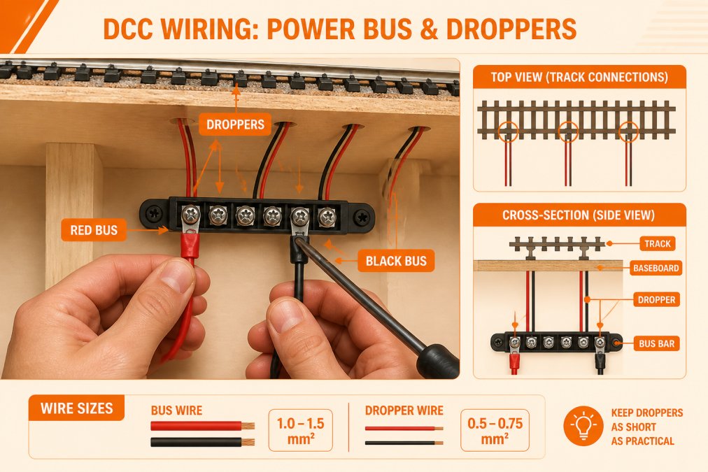
Choosing Wire Sizes for Bus, Droppers and Accessories
As a starting point, use heavier wire for the main bus than for the droppers, and lighter wire again for low-current accessories such as lighting. Layout size, run length and total current draw all affect the final choice, so treat any recommendation as a starting point rather than a rule. HobbyTrax wiring comes in a multitude of types and colours.
Soldering Model Railway Track: When and Why It Beats Rail Joiners
A common mistake is soldering with the rail already clipped into plastic sleepers. The heat softens the sleeper chairs and the rail shifts. Solder on a heat-resistant surface, use a hot iron briefly rather than a cool iron for a long time, and let the joint cool before refitting. It can be done but will most likely melt the sleepers.
DCC Power District Management: Points, Frogs, Reverse Loops and Shorts
DCC power district management is the practice of dividing a larger layout into separately protected electrical zones. If one district shorts, the rest of the layout keeps running, which makes fault finding far quicker than chasing a fault across the whole layout.
Troubleshooting Common Model Railway Wiring Problems
Work through faults in order: check the controller, then the bus, then the dropper, then the rail. Most problems are a single broken connection somewhere along that chain.
Symptom |
Likely cause |
First thing to check |
|---|---|---|
Dead section |
Broken dropper or open switch |
Voltage at the dropper, then at the rail |
Slow running far from the feed |
Voltage drop along a long bus |
Bus thickness and dropper spacing |
Intermittent running |
Dirty track or loose rail joiner |
Clean rails, then solder the joints |
Loco stalls on points |
Unpowered or wrong-polarity frog |
Frog feed and point setting |
Controller cuts out |
Short circuit or overloaded district |
Isolate districts one at a time |
Your Beginner Wiring Checklist
- Decide DC or DCC before you buy controllers
- Plan the bus route on paper first
- Use heavier wire for the bus than the droppers
- Solder droppers rather than relying on rail joiners
- Fit insulated joiners wherever you create a section
- Power frogs on electrofrog points
- Add a reversing module for any reverse loop
- Protect each district against shorts
- Keep accessory power separate from track power
- Label every wire at both ends
- Test each section as you build it, not at the end
Our owner has collected model trains for more than 50 years, and in that time has learned many lessons the hard way and that reliable wiring beneath the layout is just as important as the scenery above it. Scenery impresses visitors; wiring is what keeps the trains running when they come back next month.
Frequently Asked Questions
What is the difference between DC and DCC model railway wiring?
DC model train wiring sends variable voltage through the rails to control one train per isolated section, so you need switches and section breaks to run more than one. DCC wiring sends full power plus a digital signal to every piece of track, and each locomotive's decoder picks out its own commands. That means a DCC layout usually needs a bus wire and track droppers rather than a network of section switches.
Do I need a power bus for my model railway layout?
On a small layout, one or two feeds may be enough. As soon as your track runs beyond a few metres, a DCC bus wire with regular track droppers keeps voltage steady and avoids relying on rail joiners for continuity. A bus also makes fault finding easier, especially if you divide it into sections. Our Hydra 16-channel bus bar is one way to organise those connections neatly.
What wire size should I use for DCC bus wire and track droppers?
A common starting point is 1.0mm to 1.5mm wire for the main DCC bus on a typical home layout, with thinner wire such as 0.5mm for track droppers kept short. For decoder and lighting work, 7/0.1mm ultra-thin wire at 0.6mm diameter handles up to 0.5A. Layout length and current draw decide the final choice, so size up if your bus run is long.
Can I run DC and DCC locomotives on the same track?
A DC locomotive will not respond to DCC commands unless it has a decoder fitted, and a DCC-fitted loco on plain DC may run poorly or not at all. More importantly, never connect a DC controller and a DCC system to the same track at the same time. The conflicting power sources can damage controllers and decoders, so keep the two systems completely separate.
Why do my trains stop on points?
Locomotives often stall on points because the frog is unpowered and the wheel loses contact, or because dirt and poor rail joiners have created a dead spot. Fitting a powered frog or a stay-alive capacitor helps enormously. Check that point blades make firm contact, clean the rail tops, and add extra track droppers either side of the point rather than trusting the joiners alone.