

Last Updated: 2 November 2026
Quick Summary
Precision measuring tools are instruments that let you transfer, check and repeat a dimension to within a fraction of a millimetre. Use calipers, steel rules, squares, dividers, scribers and scale rules together, always measuring from one consistent reference edge. Get the measuring right, and the cutting gets easy.
- Digital calipers commonly display measurements in 0.01 mm increments, although their actual accuracy depends on the quality and condition of the tool.
- Close caliper jaws until they just touch the part, as squeezing soft plastic gives a false reading.
- HO scale is 1:87, so divide any real dimension in millimetres by 87.
- Cut a card or plastic template from the master measurement, never from a finished part.
- Allow for saw-blade kerf where applicable and keep the cut on the waste side of the line.
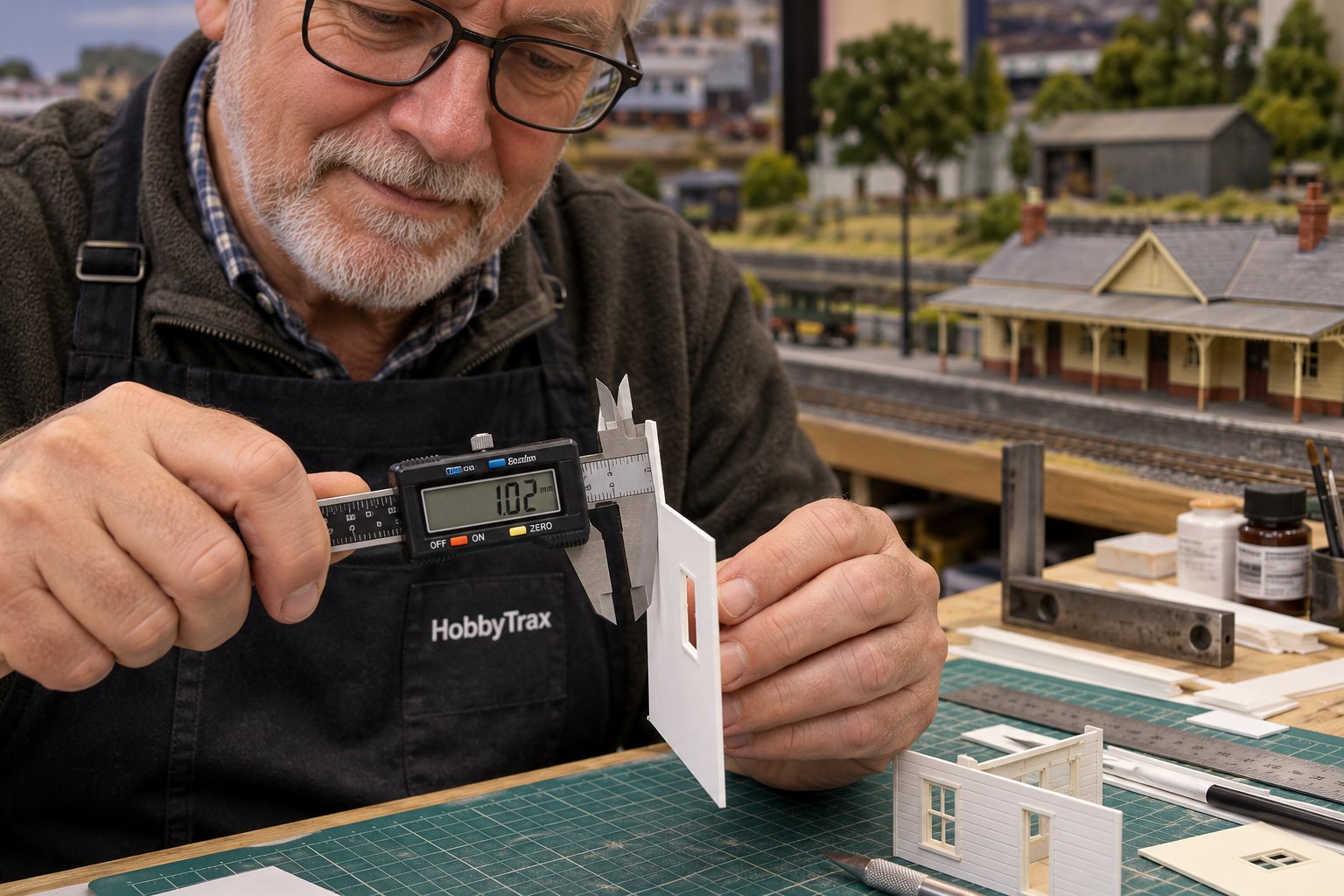
The photo of this article is of “Grandma’s cottage”. It is part of our track and reminds our owner of his mother’s cottage in the UK.
Table of Contents
- Why Accurate Measuring Matters Before You Cut
- Choosing the Right Precision Measuring Tools for the Job
- How to Use Digital Calipers for Model Making
- HO Scale Conversion and Choosing Your Scale Rule
- A Step-by-Step Shed Build: Measuring and Marking
- Templates and Cutting Stops for Scratch Building Model Railway Buildings
- Using Model Railway Building Templates for Repeatable Parts
- Common Measuring Mistakes and Your Final Checklist
- Frequently Asked Questions
Why Accurate Measuring Matters Before You Cut
A wall cut 1 mm short is a gap you will see every time you look at the layout. A roof cut 1 mm long is worse: it will not seat, and forcing it cracks the joints. Scratch building rewards patience at the bench, and precision measuring tools are how you buy that patience.
A common cause of a stalled build is not the saw. It is a measurement taken from the wrong end of a rule.
Precision measuring tools are instruments that let you transfer, check and repeat a dimension to within a fraction of a millimetre. In practice, that means calipers, steel rules, squares, dividers, scribers and scale rules working together.
Get the measuring right and the cutting gets easy. Get it wrong and no amount of sanding saves the part.
- One bad reading repeats across every part you copy from it.
- Small errors stack up fast on a structure with four walls and a roof.
- A consistent reference edge catches mistakes before they reach the saw.
Choosing the Right Precision Measuring Tools for the Job
Every tool on the bench has one job it does better than the rest. If you are just starting out, our model railway tools for beginners guide gives you a broader rundown of essential tools to compare against the measuring tools discussed here. Match the tool to the measurement and you will stop guessing.
Calipers, Rules and Squares
Digital calipers read outside, inside, depth and step dimensions. They are the go-to for material thickness and small parts. Vernier calipers do the same job without a battery, but you need good light and a steady eye to read the scale.
Steel rules are for longer, flatter measurements: wall lengths, roof spans, platform runs. Buy one with the zero at the very end and a second with a set-back zero, so a worn end never becomes your reference.
Engineer's squares check that corners are truly 90 degrees. Do not assume a pre-cut sheet has square corners. Check it, then trim if needed.
Dividers, Scribers and Marking Tools
Dividers step off equal spacings: window bays, plank lines, post positions. Set once, mark many. That is how you get repeatable parts.
Scribers score a fine line into plastic or soft metal. The line is sharper than pencil and will not rub off. Mechanical pencils in 0.5 mm suit timber and card, where a scriber would cut the grain.
A scale ruler marked 1:87 saves you converting every dimension by hand. A cutting mat with a printed grid gives you a flat, square reference surface and protects the bench.
How to Use Digital Calipers for Model Making
Calipers are the most misused tool on the bench. Four habits fix that.
- Check zero. Close the jaws fully and confirm the display reads 0.00. If it does not, reset it before you trust any reading.
- Use light jaw pressure. Close until the jaws just touch the part. Squeezing compresses soft plastic and gives you a false, smaller number.
- Measure from one reference edge. Pick a face and use it for every related measurement. Changing reference faces is how errors creep in.
- Subtract material thickness deliberately. If a wall sits inside a roof overhang, measure the overhang, then subtract the wall thickness. Write the number down.
The four readings:
- Outside: jaws over the part, for thickness and width.
- Inside: small jaws inside a gap or slot.
- Depth: the rod out the end, for how deep a recess goes.
- Step: the jaw end against a shoulder, for offset heights.
HO Scale Conversion and Choosing Your Scale Rule
HO scale is 1:87. Divide any real dimension in millimetres by 87 to get the model size. A real door 2,000 mm high becomes 23 mm in HO. Round only at the end, never mid-calculation.
OO is 1:76, so the same door comes out at about 26 mm. That difference matters: never mix HO and OO parts on one structure.
A scale rule removes the maths. Buy one marked for your scale and read model dimensions directly. HO and OO use different scale ratios, so do not assume parts are interchangeable. Compare doors, windows and other recognisable details before combining them in the same structure. We use them both interchangeably, and no one usually notices.
This is YOUR Hobby, enjoy it YOUR way!
A Step-by-Step Shed Build: Measuring and Marking
Here is the whole method on a small lineside shed, 60 mm wide, 45 mm deep and 40 mm high in HO.
- Set one master measurement. Confirm the width on the calipers and write it on the plan. Every wall copies this number.
- Mark the walls. Use the steel rule and square. Mark the front and rear walls at 60 mm wide and the side walls at 45 mm wide. Allow for the thickness of the wall material where one wall fits between another..
- Mark the windows. Set the dividers to the window spacing. Step off the centres along the wall, then square the lines down.
- Mark the roof. Add the overhang to each side, then subtract nothing: the roof sits over the walls. Check the total span against the assembled walls, not the plan.
- Test fit before cutting anything final. Cut slightly outside the marked lines where necessary, finish each edge carefully, then tape the parts together for a dry test fit before gluing.
Comparing the proportions of a commercial kit against your own plan is a fast way to sanity-check your dimensions. If you would rather build from a kit than scratch build, you can browse a wooden garden shed kit in your gauge to compare with or use alongside your own build.
Templates and Cutting Stops for Scratch Building Model Railway Buildings
One master template beats ten careful measurements. Cut a card or plastic template for each repeated part: wall, window frame, roof panel. Trace it, and every copy matches.
Cutting stops do the same job at the saw. Clamp a straight edge at the measured distance so the blade cannot wander past it. Set the stop once, cut every part against it, and the parts come out identical.
This is the same logic behind modular construction. Repeatable parts assemble into larger structures, and the jig thinking carries straight over to buildings.
Using Model Railway Building Templates for Repeatable Parts
Model railway building templates are card or plastic patterns that fix the shape and size of a repeated component so every copy matches. They remove the human error from measuring the same part twice.
Make them from the master measurement, not from a finished part. A template copied from a part copies its errors too.
- Label each template with its scale and dimension.
- Store them flat so edges stay true.
- Check the template against the plan before every batch.
Common Measuring Mistakes and Your Final Checklist
Most errors happen before the saw is switched on. Watch for these:
- Measuring from a damaged rule end. The zero has worn. Measure from the 10 mm mark and subtract 10.
- Mixing units. Millimetres and centimetres in the same plan invite a tenfold error.
- Rounding too early. Keep full numbers until the final figure.
- Forgetting blade or saw kerf. The cut removes material. Allow for it on every part.
- Assuming corners are square. Check with the engineer's square, then trim.
- Cutting before checking. Test fit first, always.
Before you cut, run this checklist:
- Calipers zeroed and reading correctly
- One reference edge chosen and used throughout
- All dimensions in millimetres
- Kerf allowance added
- Corners checked square
- Diagonals checked on the dry assembly
- Template checked against the plan
Scratch building gets easier the moment your measurements become repeatable. That is the whole game: one good number, copied accurately, again and again. Explore our tools and maintenance range for calipers, squares, rules and cutting gear, and if you are unsure what suits your scale, ask us before you buy. Share photos of your scratch-built projects with us on Facebook or email them in, and we may feature them with your permission.
A note from HobbyTrax: This article reflects our practical modelling experience and information available at the time of writing. Products, specifications and technology can change, so check current manufacturer instructions and compatibility before starting a project.
Most errors happen before the saw is switched on, so watch for these and run the checklist before every cut.
Frequently Asked Questions
How do you use digital calipers for model making?
Zero the calipers first, then apply light jaw pressure so you do not crush soft plastic. Use the large jaws for outside measurements, the small top jaws for inside openings, the depth rod for recesses and the step face for ledges. Always measure from a consistent reference edge and take two readings to confirm. For digital calipers for model making, check the battery and zero before each session, and store them closed to protect the jaws.
How do you convert full-size measurements to HO scale?
Divide the real measurement in millimetres by 87 for HO scale conversion. A 2.4 m wall becomes roughly 27.6 mm. For OO, divide by 76 instead. Keep the full-size figure written down and do the conversion once, then work in scale millimetres from that point. Rounding too early is a common error, so carry the decimal through until you mark the part.
How do you make matching walls and windows for a model building?
Take one master measurement for the wall height and width, then cut a template from card or styrene. Use that template to mark every matching wall and to position window openings. A cutting stop clamped to your rule keeps repeated cuts identical. Check diagonals on each wall to confirm they are square before assembly. Working from one master measurement and model railway building templates removes the small variations that stop parts lining up.
How can you avoid measurement errors when cutting model-making materials?
Measure from a clean reference edge, not a damaged rule end. Keep one unit system, usually millimetres, throughout. Allow for blade or saw kerf, which removes a small amount of material. Check that corners are square with an engineer's square, and test-fit before final gluing. Measure twice and cut once. If two parts must match, mark them together rather than measuring each separately.
