

Table of Contents
- Before You Wire Streetlights: Check Voltage, Polarity and Resistors
- Choosing a Power Supply for Your Streetlights
- Understanding the Model Railway LED Resistor Calculator
- Wiring Model Railway Lights in Parallel (And Why Not Series)
- Building a Model Railway Lighting Bus for Larger Layouts
- Step-by-Step: Installing and Wiring Your Streetlights
- Troubleshooting Model Railway Lights: Failed, Flickering or Dim
- Frequently Asked Questions
Last Updated: 23 October 2026
Before You Wire Streetlights: Check Voltage, Polarity and Resistors
Knowing how to wire model railway streetlights safely starts with one habit: confirm what each light actually needs before it touches a power source. The single most common mistake is connecting an unidentified light straight to a controller, an accessory output or DCC track power.
Here is what to confirm first:
- Voltage rating. Most layout lighting sold for 12V DC systems is designed to run from a regulated 12V DC supply. Check the product listing.
- Current draw. This decides how many lights one supply or switch can handle.
- Polarity. LEDs only work one way round. Reversed, they simply stay dark.
- Resistor. Some lights ship with resistors included; others don't. Never assume.
Choosing a Power Supply for Your Streetlights
A regulated accessory supply is the safest foundation for layout lighting. "Regulated" simply means the output stays steady at its rated voltage instead of drifting as the load changes.
Match the supply to your lights, not the other way around. Add up the current each light draws, then leave comfortable headroom. Products differ, so read the listing for each one.
Separate Accessory Power, DC Accessory Outputs and DCC Accessory Control
Power source |
What it suits |
Watch out for |
|---|---|---|
Separate regulated accessory supply |
Dedicated lighting bus, independent of track power |
Needs its own wiring run and isolation from track circuits |
DC controller accessory output |
Small analogue layouts with a few lights |
Output type and rating vary between controllers; check the manual |
DCC accessory control |
Switching lights from a DCC system |
Needs a suitable interface; never wire lights to track power directly |
Why DCC Track Power Is Not Ordinary DC
DCC track power is a square-wave signal carrying digital commands, not a steady DC voltage. It is not a lighting supply. Lights connected straight to it can flicker, misbehave or fail. To control streetlights from a DCC layout, use a suitable accessory interface or decoder rated for the job, and follow its instructions.
Understanding the Model Railway LED Resistor Calculator
A model railway LED resistor calculator uses Ohm's law to work out the resistor an LED needs. The formula is simple:
R = (Supply voltage − LED forward voltage) ÷ LED current
One example: a 12V DC supply, an LED with a 2V forward voltage, and a target current of 20mA (0.02A).
- 12 − 2 = 10
- 10 ÷ 0.02 = 500 ohms
The nearest common resistor value above that is 560 ohms, which gives a little safety margin. Use the actual figures from your own light's listing, never a universal number.
Wiring Model Railway Lights in Parallel (And Why Not Series)
Wiring model railway lights in parallel is the standard approach for layouts. Every light connects to the same positive and negative feed, so each receives the full supply voltage.
- Parallel: one light fails, the rest stay lit.
- Series: one light fails, the whole chain goes dark.
- Voltage drop: long, thin cable runs can dim lights at the far end. Keep runs short or use thicker cable.
Check polarity on every light before connecting it. If your supply or lights use specific wire colours, follow the product instructions rather than assuming.
Building a Model Railway Lighting Bus for Larger Layouts
A model railway lighting bus is a pair of heavier feed wires running beneath the baseboard, with lights tapped off along its length. It keeps voltage steadier and makes fault-finding far easier.
- Run the bus in a straight line under the main street or station area.
- Tap each light or small group off the bus with short droppers.
- Label each zone, for example "Station Road" or "Coal Drop Lane".
- Fit a switch or connector per zone so one fault doesn't kill the whole street.
A screw terminal block makes a tidy, serviceable junction point for each zone.

Step-by-Step: Installing and Wiring Your Streetlights
Here is the full installation sequence we recommend for how to wire model railway streetlights on HO/OO layouts.
- Plan the layout. Mark light positions and zones on the baseboard.
- Drill the mounting holes. Our Victorian street lights suit a 3mm hole, so check your own product's listing.
- Test one light first. Connect a single light to your supply and confirm it works before fitting anything permanently.
- Mount the lights. Feed wires through the holes and secure each post.
- Solder and insulate. Join wires, then cover every joint with heat-shrink.
- Connect to the bus or terminal block. Match polarity throughout.
- Test the zone. Power up one zone at a time and check every light.
- Label and tidy. Mark zones and secure loose cable.
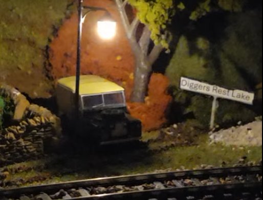
Mounting Lights Without Damaging the Wires
Drill the hole slightly larger than the wire bundle, not the post. Feed wires through gently, and never pull on the lamp head to drag cable through. Leave a small service loop under the baseboard so future work doesn't tug the joint.

Soldering and Insulating Your Joints
- Tin the wire ends before joining.
- Keep heat brief; LEDs dislike prolonged heat.
- Slide heat-shrink on before soldering, then shrink it over the joint.
- Work in a ventilated space and let the iron cool safely.
Troubleshooting Model Railway Lights: Failed, Flickering or Dim
Troubleshooting model railway lights usually comes down to four culprits: polarity, a bad joint, a wrong resistor, or too much voltage drop.
- Dead light: check polarity first, then the resistor and joint.
- Flickering: suspect a loose joint, poor connector contact or an unstable supply.
- Dim light: check for voltage drop on long runs, or a resistor value that's too high.
- Several dead at once: check the zone switch and bus connection.
Swap a suspect light with a known working one to isolate the fault fast.
Frequently Asked Questions
Can you connect LED streetlights directly to DCC track power?
No. DCC track power is a square-wave signal, not a steady DC voltage, so connecting a streetlight directly to the rails can destroy the LED. Streetlights should run from a separate regulated DC supply or through a dedicated DCC accessory controller or function decoder. Check the light's rated voltage and whether a resistor is supplied, then confirm your chosen output matches that rating before connecting anything.
Should model railway lights be wired in series or parallel?
Wire streetlights in parallel. In a parallel circuit every light receives the full supply voltage, so if one lamp fails the rest stay lit and each can be switched separately. Series wiring divides the voltage between lights and one failure breaks the whole chain, which is awkward to diagnose on a layout. Parallel wiring does draw more total current, so add up each light's draw and check it against your supply's rating.
Why are my model railway streetlights flickering or dim?
Flickering usually points to a loose joint, a wire nicked during mounting, or an overloaded supply. Dim lights often mean the resistor value is too high for the LED, the supply voltage is lower than expected, or too many lights share one output. Isolate power, test one light on its own, then check each joint and your total current draw before changing anything.