

Quick Summary
Power districts are separate, electrically isolated sections of track, each with its own feed, so you can switch one part of your layout off while the rest keeps running. Plan them from the start, keep each district manageable, and test every rail gap before fitting. A short then shuts down only its own district. (When each district is connected through its own DCC circuit breaker or protected booster output, a short can shut down that district while the rest of the layout continues operating. A manually switched bus bar helps isolate sections for testing but does not replace automatic circuit protection.)
- Split the layout into districts at yards, sidings, stations and passing loops.
- Keep districts small so a fault leaves a manageable area to check.
- Connect each district to its own output on the 16-terminal bus bar.
- Cut a gap at every boundary and test it with a multimeter for continuity.
- Test each district alone before running locomotives across the whole layout.
Table of Contents
- 1) What Power Districts Are and Why Your Layout Needs Them
- 2) Planning Your Power District Layout Before You Cut a Wire
- Tools, Materials and Wire You Will Need
- 3) Wiring the Main DCC Bus and Dropper Connections
- 4) Installing Gaps and Feeding Each Power District
- 5) Adding a DCC Circuit Breaker for Each Power District
- 6) Model Railway Short Circuit Troubleshooting and Common Mistakes
- 7) Testing Your Power Districts and Booking Your Next Layout Step
- Frequently Asked Questions
7 Steps to Wire Model Railway Track Power Districts
Last Updated: November 1, 2026
1) What Power Districts Are and Why Your Layout Needs Them
Power districts are separate, electrically isolated sections of track, each with its own feed. A power district lets you switch one part of your layout off while the rest keeps running, making faults much easier to find.
On a DCC layout, the whole track normally shares one main bus. Without districts, one short anywhere can stop every train on the layout. Dividing the track into districts means a short in one yard only shuts down that yard.
We recommend planning districts from the start rather than adding them after the scenery is down. Retrofitting gaps into finished track is fiddly and easy to get wrong. A layout with well-chosen districts is also much more pleasant to run, since you can work on one area while another stays live.
2) Planning Your Power District Layout Before You Cut a Wire
Sketch your layout first and mark every point where track sections meet. Each isolated section becomes a candidate for its own district.
Good places to split districts include:
- Yards and sidings, so shunting work can be isolated
- Each station or passing loop
- The main line, split into manageable lengths
- Any area with its own turnouts, motors or accessories (Turnout motors, lighting and accessories are not necessarily good reasons for creating track districts on their own. Where practical, recommend a separate accessory bus so an accessory fault does not interrupt train operation).
Keep a district manageable enough that a fault leaves you a manageable area to check. A common mistake is making districts too large because it feels tidier on paper. Smaller districts save time when fault finding, as you have less area to check.
Label each district on your plan. Give it a name and note what it feeds. You will thank yourself when wiring.
Tools, Materials and Wire You Will Need
Gather everything before you start so you don't stop mid-job to hunt for parts.
- A DCC bus bar with isolation, such as the Hydra 16-Channel DC/DCC Bus Bar with Isolation, which provides 16 output terminals and per-section isolation
- Finer wire for droppers and short runs (I would not suggest as fine as the decoder wire 7/0.1mm Ultra-Thin DCC Decoder Wire - 10m, as it is too thin).
- Black Nylon Cable Ties / Zip Ties - 25 Pack to keep wiring tidy under the baseboard
- A helpful reference: the Hobby Trax Helpsheet - DCC Bus wiring, which is free and emailed to you
Use colour coding consistently to keep track of your circuits. Choose one colour scheme and apply it across the layout. Check the specification of any wire or bus bar against its listing before fitting.


3) Wiring the Main DCC Bus and Dropper Connections
The main bus is the pair of wires that carries power from your command station to the track. Run it along the length of the baseboard, then drop a feed to each district. Connect multiple short droppers from each district bus to the rails to provide reliable power throughout that section.
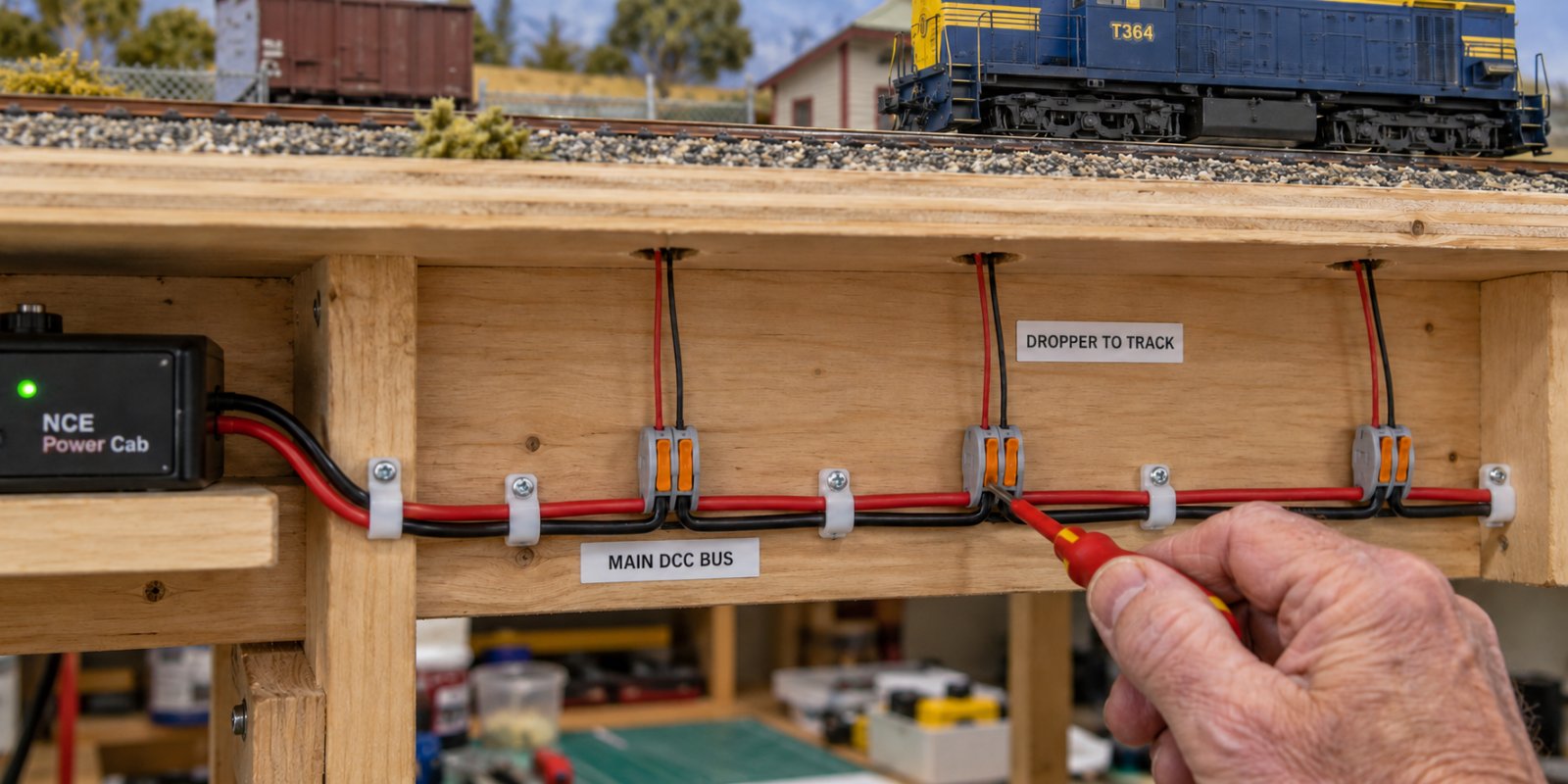
Connect the bus to the power-in terminals of your bus bar. Then run a dropper from each of the 16 output terminals to its district. Keep droppers short where you can, and avoid tying them tightly to the bus, since you may need to modify them later.
Watch out: Don't overtighten cable ties around the bus wiring. Leave room for the wires to move, particularly where you may need to change things later.
The table below summarises the key wiring components and checks covered in this section and the one that follows.
Item |
Role |
Key check |
|---|---|---|
Main DCC bus |
Carries power from the command station to the track |
Run along the baseboard |
Droppers |
Feed power from the bus to each district |
Keep short where you can |
Bus bar outputs |
16 terminals, one per district feed |
Use one output per district |
Rail gaps |
Electrically separate neighbouring districts |
Test with a multimeter on continuity |
Cable ties |
Keep wiring tidy under the baseboard |
Do not overtighten |
4) Installing Gaps and Feeding Each Power District
Each district must be electrically separated from its neighbours. Cut a small gap in the rail (or use isolation rails) at every boundary, then check that the rail on each side is isolated before going further.
Feed each district from its own output on the bus bar. The Hydra board's isolate function switches off everything connected to a given output, which is what lets you isolate a section during a fault. For this to work properly in DCC mode, each section needs its own isolated feed, powered through a single output.
Test each gap with a multimeter set to continuity before you reconnect anything. A gap that is not fully cut will let power bridge into the next district and defeat the whole purpose.
5) Adding a DCC Circuit Breaker for Each Power District
A circuit breaker is a device that cuts power to a district automatically when it detects a short. Some modellers fit one per district, while others use the simpler approach of an on/off switch for each feed.
Either way, the principle is the same: a short in one district should not take down the rest. Check that any breaker or switch you use is rated for the current your district draws, and confirm this against the manufacturer's specification.
6) Model Railway Short Circuit Troubleshooting and Common Mistakes
Shorts are a common headache once districts are wired. If you want a deeper look at the wiring methods behind them, our advanced DCC wiring guide covers the techniques in more detail. Work through them methodically.
- Switch off the isolate function for each district in turn until the fault clears. The district you just switched off contains the short.
- Check for stray strands of wire bridging the rails, especially near droppers and rail joiners.
- Inspect the gaps for filings or solder blobs that have closed them.
- Look at the wiring underneath for a pinched or bared wire touching the baseboard or a metal part.
Common mistakes include:
- Gaps that look cut but still conduct
- Droppers connected to the wrong output, sending power to the wrong district
- Forgetting that power districts are separate from manually isolated power districts, which you can switch off using a bus bar or switch. (A power district is an electrically separated section of track with its own power feed.)
- Overloading a single output with too many locomotives or accessories
7) Testing Your Power Districts and Booking Your Next Layout Step
Test each district on its own before running trains across the layout. Power only one district at a time, run a locomotive through it, then switch it off and confirm the rest of the layout is unaffected.
Once every district passes, run a locomotive across the boundaries between districts. It should cross each gap without stalling or flickering.
When you're ready for the next stage, the Hydra bus bar covers the isolation setup in detail. Share a photo of your finished districts with us, and we'd love to see how your layout is coming along.
A note from HobbyTrax: This article reflects our practical modelling experience and information available at the time of writing. Products, specifications and technology can change, so check current manufacturer instructions and compatibility before starting a project.
Frequently Asked Questions
What is a power district on a DCC model railway?
A power district is a section of track that can be switched on or off independently of the rest of the layout. Each district is fed from the DCC bus through its own wiring, and a fault in one district should not stop trains running elsewhere. Power districts make fault finding far quicker because you only need to test the section where a short is occurring. They are usually separate from the wiring used for control signals, so each district must be connected correctly to the DCC bus to work reliably.
How many power districts does a model railway need?
There is no fixed number. Most home layouts work well with several districts, typically divided by station throats, yards, staging loops or any section where you might need to isolate a problem. Smaller layouts may only need two or three, while larger layouts often benefit from one district per major area. Plan the boundaries around how you operate the layout rather than simply counting baseboards, and keep each district small enough that a short is easy to trace.
Can one DCC booster supply multiple power districts?
Yes. A single DCC booster can feed several power districts, provided the total current drawn by all of them stays within the booster's rated output. Each district still needs its own feed from the bus and its own means of isolation or protection, such as a circuit breaker. Check the booster's current rating and your planned load before connecting everything, and never assume a booster can support unlimited districts without verifying its specification.
How do you find a short circuit in a DCC power district?
Start by isolating the district where the short is occurring, so the rest of the layout continues to run. Then check for obvious problems such as wires touching, loose rail joiners, stray solder or track gaps bridged by metal debris. Inspect the wiring at each dropper and at the gap joins before testing further. Work through the district methodically, isolating smaller sections where possible, and always disconnect power before handling wiring.
