

Last Updated: November 9, 2026
Quick Summary
The essential tools for a DCC decoder installation are magnification and good lighting, precision screwdrivers, fine tweezers, suitable wire strippers, a temperature-controlled soldering iron with fine solder, heat-shrink tubing and a multimeter. Each solves a specific problem, and skipping any shifts risk onto the locomotive.
- Assess mechanical condition, socket or hardwire needs, motor suitability and available space before starting.
- A magnifier of around 2x to 3x is often enough for decoder work.
- Set wire strippers so jaws close on insulation without biting the 30-gauge conductor.
- Check continuity with the multimeter, power disconnected, before connecting anything.
- Test decoders before fitting and again before closing the body.
Table of Contents
- Why Precision Tools Decide Whether a DCC Decoder Installation Succeeds
- The Essential Tools for DCC Decoder Installation
- Sockets, Hardwiring and Motor Isolation Explained
- Model Railway Soldering Tips for Delicate Locomotive Wiring
- Testing DCC Decoders After Installation
- Managing Wiring, Insulation and Tight Spaces
- Send Us Your Locomotive for Assessment
- Frequently Asked Questions
Why Precision Tools Decide Whether a DCC Decoder Installation Succeeds
A DCC decoder installation succeeds or fails on the quality of the tools in your hands. A locomotive that arrives with lifted pads, melted wiring or bridged solder joints usually points back to the tools and technique rather than the iron alone.
Precision matters because the components are tiny. Decoder pads sit a few millimetres apart, and a fine 30 AWG decoder wire is easily damaged and requires tools suited to very small conductors..
What We Check Before Any Decoder Goes In
Before we touch a soldering iron, we run a short assessment. It saves far more time than it costs.
- Mechanical condition: does the chassis roll freely, are the gears intact, are the pickups clean?
- Socket or hardwire: is the locomotive DCC-ready with a socket, or does it need hardwiring?
- Motor suitability: what type of motor is fitted, and what current does it draw?
A locomotive that runs poorly on DC is unlikely to run better on DCC, so it is worth addressing the mechanics first.
The Essential Tools for DCC Decoder Installation
The essential tools for a DCC decoder installation are magnification and good lighting, precision screwdrivers, fine tweezers, suitable wire strippers, a temperature-controlled soldering iron with fine solder, heat-shrink tubing and a multimeter.
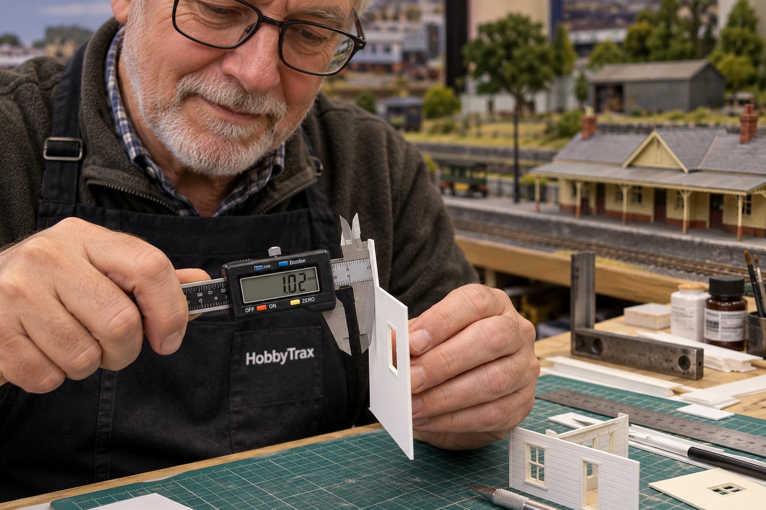
Magnification and Lighting
You cannot solder what you cannot see. A magnifying lamp or a headband magnifier lets you inspect a decoder pad and check a solder joint before and after the iron touches it.
The ergonomics are where most beginners come unstuck. Working at N or OO scale means holding your head close to the work for long stretches, and a fixed bench lamp forces you into awkward angles.
Precision Screwdrivers, Tweezers and Wire Strippers
Body clips and tiny screws demand screwdrivers that fit properly. Our Model Locomotive Body Removal Pry Tools slide between body and chassis to release clips with a controlled gap rather than a forced one.
Fine tweezers hold a wire in place while your other hand works the iron. Wire strippers need to suit the wire gauge, and 30-gauge decoder wire is easy to nick with the wrong tool.
Soldering Irons, Solder and Heat-Shrink
A temperature-controlled station lets you set a temperature that melts solder without cooking nearby plastic. A dual-alloy rosin-core solder wire set in 0.8mm is suited to small joints. Our 0.8 mm rosin-core solder can be used for locomotive wiring when fed sparingly. For extremely small decoder pads, some installers may prefer a finer solder for greater control. For fine electronic work, Sn63Pb37 Leaded Solder Paste which has excellent solder flow, reliable electrical connections and a low melting point

Heat-shrink tubing insulates a joint and adds strain relief. Kapton tape is thin, heat-resistant and useful for holding a decoder or protecting components during soldering. A Kapton tape is available in several widths for tight locomotive bodies.

Protecting Delicate Decoder Chips from Static
Decoder chips are sensitive to electrostatic discharge, and a spark you cannot feel can damage an input. A grounded anti-static mat under the work and a wrist strap connected to the same ground point give static a safe path away from the decoder. Avoid working on carpet in synthetic clothing, and handle a decoder by its edges rather than its pins.
Keeping Fine Tools Working
Precision tools can drift out of adjustment over time, so it is worth checking them regularly. A fine soldering tip oxidises and stops taking solder; clean it on a brass wool pad rather than a wet sponge, re-tin it before storing, and replace it once the plating wears through. Wire strippers should be re-checked against a scrap length whenever you change wire gauge.
Tools to Avoid for Decoder Work
Some everyday tools can cause more damage than they save. Standard household pliers crush insulation and flatten fine wire; precision flush cutters shear cleanly instead. A hardware-store soldering iron with no temperature control climbs past the point where plastic softens. A craft knife used to strip wire nicks the conductor.
Here is the precision kit we rely on, and what each item is there to do.
Tool |
Purpose |
Note |
|---|---|---|
Magnifying lamp or headband magnifier |
Inspect decoder pads and solder joints |
Around 2x to 3x is often enough |
Precision screwdrivers |
Release body clips and tiny screws |
A poor fit slips and scratches paintwork |
Fine tweezers |
Hold wire in place while soldering |
Check tips meet squarely before use |
Wire strippers |
Strip 30-gauge decoder wire |
Set jaws to avoid nicking the conductor |
Temperature-controlled soldering iron |
Melt solder without cooking nearby plastic |
Uncontrolled irons climb past safe heat |
0.8mm dual-alloy rosin-core solder |
Suited to small joints |
Feed solder to the work, not the tip |
Sn63Pb37 solder paste |
Particularly useful for surface-mount components, small PCB pads |
Do not overheat. Too much can create solder bridges |
Heat-shrink tubing |
Insulates a joint and adds strain relief |
Choose based on space available |
Multimeter |
Check continuity and shorts with power off |
Catches faults before damage occurs |
Sockets, Hardwiring and Motor Isolation Explained
A DCC-ready locomotive has a socket, most commonly the 8-pin NEM 652, which lets a decoder plug in without soldering to the locomotive at all.
Motor isolation is the step that catches people out. If you are weighing up socket versus hardwired work in an older model, our guide to DCC decoders for older locomotives walks through which decoders suit which models.
No decoder fits every locomotive. Motor type, current draw and physical space all decide it, so check the decoder's rating against your locomotive rather than assuming.
Model Railway Soldering Tips for Delicate Locomotive Wiring
Good soldering technique for model railway wiring comes down to heat control and preparation. Clean the joint, tin the iron, heat the work and feed solder to the work rather than the tip. Remove the iron the moment the solder flows. The difference between a reliable joint and a lifted pad is usually measured in a second or two of contact time, so the technique matters as much as the iron.
Preparing the Joint and the Iron
A joint solders cleanly only if both surfaces are clean. Wipe the pad and the wire with isopropyl alcohol and let them dry. Tin the iron tip with a thin film of solder so heat transfers across the whole contact area rather than a single point. Tin the wire end separately before bringing it to the pad; a pre-tinned wire and a pre-tinned pad need only a brief touch to flow together.
Controlling Heat Around Plastic
Protect plastic parts with Kapton tape or a small heat sink where appropriate. Work in short bursts and let the joint cool between attempts. On a locomotive, the parts most at risk are the body shell, the insulation on adjacent wires and any plastic clip near the motor. Tape the shell back out of the way, and clip a heat sink onto a wire a few millimetres from the joint so heat wicks away before it reaches the insulation.
Inspecting Every Joint
A good joint should be smooth and properly flowed around the wire and pad, without loose strands, sharp projections or a rounded blob sitting on the surface. Traditional leaded solder is usually shiny, while some lead-free solders can appear slightly matt even when the joint is sound. Watch out: a solder bridge between two decoder pads is easy to create and hard to spot, so check the gap between adjacent pads with a magnifier and confirm with a multimeter on continuity before you connect the decoder.
Checking for Shorts with Power Disconnected
Before any power goes near the locomotive, set the multimeter to continuity and check between the motor terminals, between each motor terminal and the frame, and across the pickup wires. A reading where there should be none means a short, and the decoder must not be connected until it is found and cleared. This check is the single most useful habit in decoder work, because it catches the fault before it becomes a damaged decoder.
Securing Wiring Clear of Moving Parts
Route the harness clear of the motor, gears and any moving valve gear, and secure it so it cannot chafe against the frame. A wire that touches a spinning motor or a gear will wear through its insulation and short. Keep runs short, dress them along the chassis with tape or putty, and check clearance by turning the mechanism by hand before the body goes back on.
Testing DCC Decoders After Installation
Test before you fit, and test again before you close the body. A DCC decoder tester lets you plug in 6-pin, 8-pin and 21-pin decoders and check motor and lighting functions outside the locomotive, which can help rule out a faulty decoder before you look for installation faults.

With power disconnected, check for shorts with a multimeter. Then place the locomotive on the programming track and follow the decoder and command station instructions for address and basic configuration. If something misbehaves, stop and investigate rather than reprogramming repeatedly.
Managing Wiring, Insulation and Tight Spaces
Tidy wiring is reliable wiring. Route the harness clear of moving parts, keep it away from the motor and gears, and secure it so it cannot chafe. Ultra-thin decoder wire is available in ten colours to help identify runs, and decoder putty can hold a decoder or speaker in place without permanent adhesive.
Insulate every exposed joint. Kapton tape and heat-shrink both work; choose based on the space available. Before refitting the body, check that nothing is pinched.
Send Us Your Locomotive for Assessment
If any part of this feels beyond your comfort level, that is a sensible place to stop. Send us the locomotive model, the symptoms and the upgrade you have in mind, and we will assess the mechanical condition, the socket or hardwiring requirements and the space available.
Prefer to speak with us? Call (07) 3566 1476.
A note from HobbyTrax: This article reflects our practical modelling experience and information available at the time of writing. Products, specifications and technology can change, so check current manufacturer instructions and compatibility before starting a project.
Frequently Asked Questions
What tools do I need to install a DCC decoder in an HO locomotive?
At minimum you need a temperature-controlled soldering iron with a fine tip, 0.8mm rosin-core solder, fine tweezers, precision screwdrivers, wire strippers rated for small wire, a multimeter for continuity testing, and magnification with good lighting. Add Kapton tape and heat-shrink tubing for insulation, plus thin decoder wire if you are hardwiring. A decoder tester is worth having so you can confirm a decoder works before it goes anywhere near the locomotive.
How do I avoid damaging locomotive wiring during a decoder installation?
Work with the track power off, use tools sized for the job and never force a body or a plug. Strip only a short amount of insulation, tin wires before joining them, and keep heat away from plastic. Use an appropriate temperature that allows the solder to flow promptly, then remove the iron as soon as the joint is formed. Follow the solder, decoder and equipment manufacturers’ guidance. Secure the wiring loom clear of moving parts with Kapton tape or a small cable tie, and check for shorts with a multimeter before applying power.
What is the difference between DCC-ready and DCC-fitted locomotives?
A DCC-ready locomotive has a socket, commonly the 8-pin NEM 652, and the motor is already isolated so a decoder can be plugged in. A DCC-fitted locomotive already has a decoder installed. A locomotive with neither needs hardwiring, which usually means isolating the motor from the chassis and soldering the decoder harness directly. Check your model's documentation before buying a decoder.
Why is a temperature-controlled soldering iron important for model trains?
A fixed-output hardware store iron keeps pumping heat into a small joint, which can melt sleepers, distort plastic bodies and lift fine PCB pads. A temperature-controlled station holds a set temperature, so solder flows quickly and the iron comes off sooner. That control matters most on 30-gauge decoder wire and tiny pads where a second too long causes damage. Use a fine tip and keep it clean and tinned.
How do I check for shorts after installing a DCC decoder?
With the decoder disconnected and all power removed, use the multimeter to confirm that neither motor terminal has continuity to either rail pickup or the metal chassis. Some continuity between the two motor terminals is normal because you are measuring through the motor windings. Also inspect for unintended connections between adjacent decoder pads and exposed wiring.
