

Last Updated: 14 November 2026
Quick Summary
To wire LEDs for a model railway safely, never connect a bare LED directly to a power supply or DCC track power. Instead, feed each LED from a regulated DC supply through a series resistor, with the anode to positive and cathode to negative, and give every parallel branch its own resistor.
- Calculate the resistor with R = (supply voltage − LED forward voltage) ÷ desired current, checking your LED's forward voltage.
- On a 12V supply with a 2V LED at 10mA, the resistor works out at 1000 ohms, or 1kΩ.
- Run lighting on DCC layouts from a separate regulated accessory supply, never from the track bus.
- Do not use one resistor ahead of several parallel LEDs; give each branch its own resistor.
- Insulate every joint with heat-shrink and test each LED with a multi-meter before burying it under scenery.
Table of Contents
- The One Rule Before You Wire LEDs for a Model Railway
- Model Railway LED Polarity: Anode, Cathode and the Basic Circuit
- Your 12V LED Resistor Calculation, Worked Through
- LED Wiring in Series and Parallel: Which to Use Where
- Choosing a DCC Layout Accessory Power Supply
- Soldering, Wire Colours and Insulation Done Properly
- Common Mistakes and How to Fault-Find Them
- Explore Our Lighting and Electrical Components
- Frequently Asked Questions
The One Rule Before You Wire LEDs for a Model Railway
Never connect a bare LED straight to a power supply or to DCC track power. An LED has almost no internal resistance of its own, so it will try to draw far more current than it can survive. The result is a brief flash, then a dead component.
The fix is simple: every LED needs a resistor in series with it. That resistor sets the current to a safe level. This guide covers how to wire LEDs for a model railway on both DC and DCC layouts, from buildings and platforms to street lights, signals and control panels.
Below, we'll show you the exact circuit, a worked 12V LED resistor calculation, and the mistakes that burn out more LEDs than anything else.
Model Railway LED Polarity: Anode, Cathode and the Basic Circuit
An LED is a light-emitting diode, which means it only works one way around. The anode is the positive leg. The cathode is the negative leg and is usually the shorter one, often with a flat spot on the body rim.
Get the polarity backwards and the LED simply won't light. It usually won't be damaged at low voltage, but it will look like a faulty component.
The basic circuit is three parts in a row:
- A regulated DC supply, such as a 12V DC plug pack
- A series resistor to limit current
- The LED itself, anode toward the positive side
If you want the full walkthrough beyond these polarity basics, our step-by-step LED wiring guide covers the whole process in detail.
Your 12V LED Resistor Calculation, Worked Through
The formula is R = (supply voltage − LED forward voltage) ÷ desired current.
Forward voltage is the small voltage the LED itself drops when lit. It varies by colour and by LED, so always check the manufacturer's figure rather than assuming.
Here is a worked example on a 12V DC supply:
- Supply voltage: 12V
- LED forward voltage: 2V (check your LED's rating)
- Desired current: 10mA, written as 0.01A
- R = (12 − 2) ÷ 0.01 = 1000 ohms, or 1kΩ
The resistor must also have a suitable power rating. In this example, it dissipates approximately 0.1 watts, so a ¼-watt (0.25W) resistor provides a sensible safety margin. If you use a lower resistor value or increase the LED current, recalculate the resistor’s power requirement before connecting it.
Running LEDs well below their maximum rating gives a more realistic glow and helps the LED last. Maximum brightness is rarely what a layout needs. For houses, street lamps, yards, sidings, we always go slightly more, and we recommend 2.2k, which gives a slightly brighter light, while 3.3kΩ produces a softer glow.
To make it simple we also have a number of Built-in resistor LEDs.
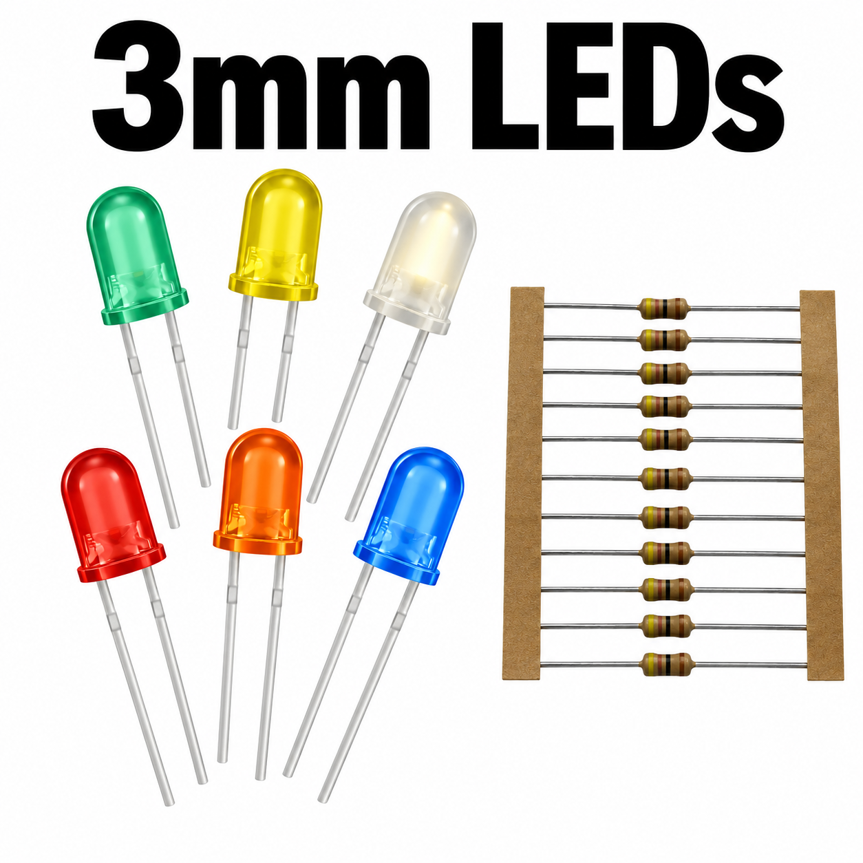
Once the maths is done, a 3mm LED kit with resistors for 12V DC lets you put it straight into practice, with resistors included.
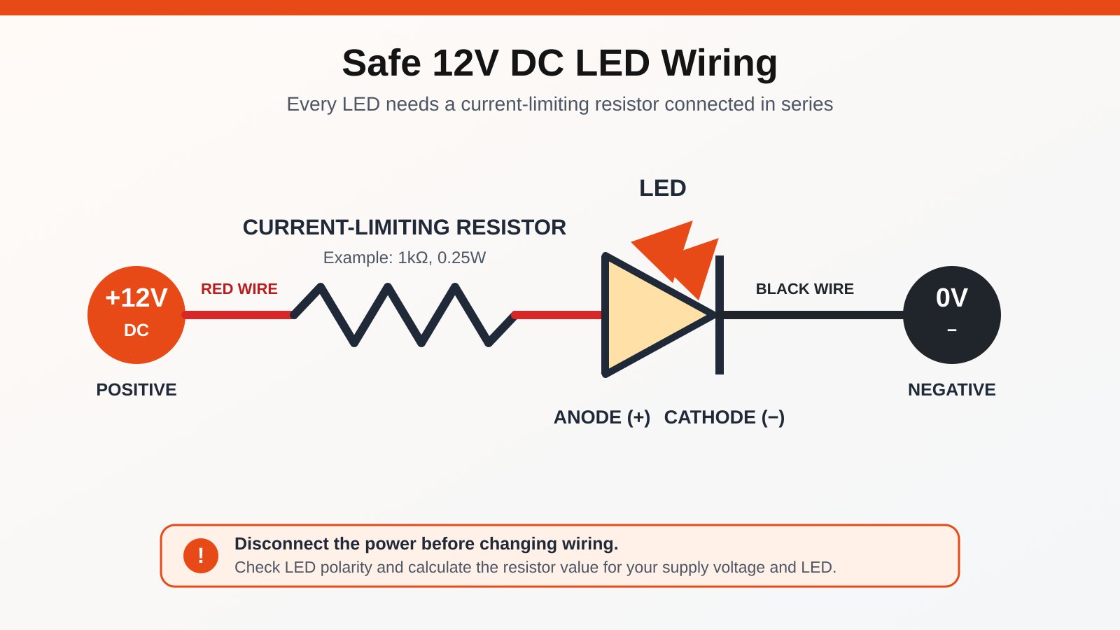
Basic 12V DC LED wiring: Connect the current-limiting resistor in series between the positive supply and the LED anode. Connect the LED cathode to the negative supply.
Note: Some multi-meters do not provide enough test voltage to illuminate white or blue LEDs. If the meter displays “OL” in both directions, this does not necessarily mean the LED has failed. Confirm the LED using a suitable low-voltage supply and the correct series resistor before replacing it.
LED Wiring in Series and Parallel: Which to Use Where
Series wiring chains LEDs one after another, so the same current flows through all of them. Their forward voltages add up, which means the supply must exceed the combined total.
Parallel wiring gives each LED its own branch off a common positive and negative feed. This is where most people go wrong.
Wiring method |
Current path |
Resistor placement |
Best for |
|---|---|---|---|
Series |
One path through all LEDs |
One resistor for the chain |
Small groups on one supply |
Parallel |
Separate branch per LED |
One resistor per branch |
Buildings, platforms, street lights |
Do not use a single resistor ahead of several parallel LEDs. Each LED draws slightly different current, so one branch can hog the supply and fail. Give every parallel branch its own resistor.
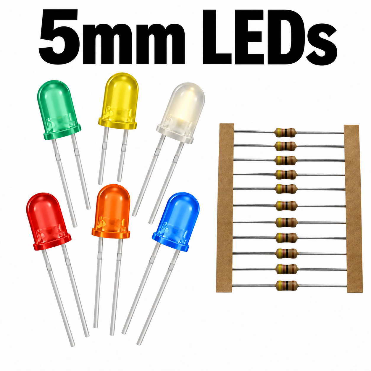
Planning parallel branches for buildings or platforms? A 5mm LED kit with resistors for 12V DC gives you ten LEDs with resistors included to build those circuits.
Choosing a DCC Layout Accessory Power Supply
On a DCC layout, run your lighting from a separate regulated accessory supply. DCC track power is not ordinary DC. It is a high-frequency square wave carrying commands, and it must never connect directly to an LED. Treat the track bus and the lighting bus as two separate systems that happen to share a layout.
A practical arrangement looks like this:
- Keep the DCC command station and booster feeding track only.
- Add a dedicated regulated DC supply for lighting, sized to your total load.
- Run a lighting bus from that supply, with each building or section fed from it through its own resistor.
- Switch and fuse or protect the lighting bus separately from the track.
Sizing the supply is simple arithmetic. Add up the current for every LED on the bus. If you have 40 LEDs each running at 10mA, that is 40 × 0.01A = 0.4A, plus a margin for future additions. Choose a regulated supply rated comfortably above that total, and check its voltage matches the resistor calculations you have already done. A supply rated at 12V DC and 1A will happily run a modest building and platform lighting scheme with headroom.
Accessory outputs are not all the same. Some DCC systems provide accessory outputs intended for point motors or signals, and these may be short pulses, AC, or a different voltage from a smooth DC lighting supply. Do not assume an accessory output is a clean DC feed for LEDs. Check the manufacturer's documentation for the output type and voltage before connecting anything.
Track-powered lighting is possible but is not a beginner's first project. If you want to take power from the rails, you need a suitable bridge rectifier to convert the DCC signal to DC, plus a resistor and correctly rated components, all following the manufacturer's instructions. The rectifier, its voltage rating and the smoothing (if any) must suit the DCC voltage on your layout.
Watch out: never tap DCC track power straight to an LED or a lighting bus without rectification and current limiting. The square wave will destroy a bare LED almost instantly.
For deeper detail on accessory and track wiring, our advanced DCC wiring techniques guide is worth reading before you commit.
Soldering, Wire Colours and Insulation Done Properly
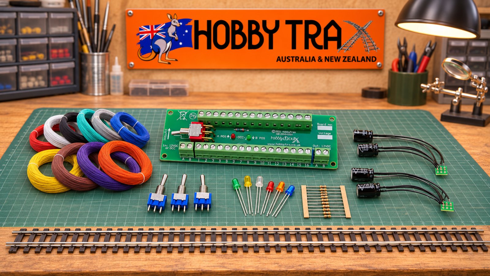
Good joints and tidy insulation prevent most lighting faults. A few habits make the difference:
- Tin the wire and the LED leg before joining them
- Keep heat brief so you don't damage the LED
- Slide heat-shrink tubing over the joint before soldering, then shrink it after
- Pick a consistent wire colour scheme and write it down
- Test each LED with a multi-meter before you bury it under scenery
A common mistake is skipping the heat-shrink and leaving bare joints that short against track or metal structures. Insulate every joint.
Common Mistakes and How to Fault-Find Them
Most LED faults come down to a short list, and a multi-meter turns guesswork into a procedure. Work through these in order before you assume a component is dead.
The common mistakes:
- Reversed polarity: the LED is fitted the wrong way around, so it will not light
- Missing or undersized resistor: the LED draws too much current and fails or dims prematurely
- Excessive brightness: the resistor value is too low for a realistic glow
- Exposed joints: bare wire or LED legs short against track, metal structures or each other
- Voltage drop: long lighting bus runs dim the LEDs at the far end
- Overloaded supply: the total current draw exceeds what the supply can deliver
A systematic testing procedure:
- Isolate the circuit. Switch off and disconnect the lighting supply before touching, disconnecting or altering any wiring.
- Check the supply first. Reconnect and switch on the supply only when you are ready to measure voltage. Set the multi-meterto DC volts and confirm that the regulated supply is delivering its rated voltage at the lighting bus origin. Switch the power off again before continuing with resistance, continuity or diode tests.
- Check polarity and the LED. With the circuit isolated, use the multi-meter’s diode-test function across the LED. A working LED will normally show a forward-voltage reading in one direction and an open reading when the probes are reversed. Some multi-meters do not provide enough test voltage to illuminate white or blue LEDs, so an “OL” reading in both directions does not necessarily mean the LED has failed. If necessary, confirm it using a suitable low-voltage DC supply and the correct series resistor.
- Check the resistor. With the power disconnected, disconnect one end of the resistor from the circuit before measuring it on the multi-meter’s resistance setting. Compare the reading with the calculated value. Measuring it while it remains connected can produce an inaccurate result because other components may provide parallel paths.
- Check for shorts. With the circuit isolated, test between the positive and negative lighting-bus conductors. A very low resistance reading may indicate an exposed joint, crossed wiring or another short circuit. Remember that connected electronic modules or capacitors can affect the reading, so disconnect them if necessary.
- Check voltage drop along the bus. With the circuit powered and the multi-meterset to DC volts, measure the voltage at the supply end and again at the far end while the lights are operating. A significant difference can indicate wire that is too thin, a run that is too long, a poor connection or an excessive load.
- Check total current. Current must be measured with the multi-meter connected in series, which requires opening the circuit and inserting the meter into the current path. Never connect a meter set to current directly across the positive and negative supply terminals. Use the correct meter socket, begin on the highest suitable current range and observe the meter’s fuse and current limits. If you are unsure how to do this safely, calculate the expected current from the number of LEDs and their individual operating currents instead.
Watch out: If a whole lighting section fails at once, the fault is more likely to be in the power supply, switch, fuse, connection or lighting bus than in a single LED. Check the common supply path before replacing individual LEDs.
If a whole section of lighting fails, our streetlight wiring guide covers practical installation and troubleshooting for lighting circuits.
Explore Our Lighting and Electrical Components
Wiring LEDs safely comes down to a handful of habits: always use a resistor, respect polarity, give each parallel branch its own resistor, and keep DCC track power away from bare LEDs. Get those right and your lighting will be reliable for years.
If you are unsure which kit or resistor suits your layout, ask us before you buy. We are happy to help you check compatibility.
A note from HobbyTrax: This article reflects our practical modelling experience and information available at the time of writing. Products, specifications and technology can change, so check current manufacturer instructions and compatibility before starting a project.
Ready to light up your layout? Explore our lighting and electrical components, or get in touch and we will help you choose the right LEDs, resistors and wiring for your project.
Frequently Asked Questions
Do model railway LEDs need a resistor?
Yes, every LED needs a resistor (or another current-limiting method) in series unless it is a kit supplied with one already matched. A bare LED connected straight to a supply or DCC track will draw too much current and fail, often within seconds. Use R = (supply voltage - LED forward voltage) / desired current, and check the forward voltage on the LED's listing rather than guessing. Our LED kits include resistors for 9-13V DC operation.
Can you connect LEDs directly to DCC track power?
No. DCC track power is a square-wave signal, not ordinary DC, so it must not connect directly to an LED. For DCC layouts, run lighting from a separate regulated accessory supply. If you want track-powered lighting, you need a suitable bridge rectifier, a resistor and correctly rated components, wired following the manufacturer's instructions. Keep the lighting bus separate from track feeds and label it clearly so nobody plugs an LED into the wrong source later.
Should model railway LEDs be wired in series or parallel?
Parallel wiring is the usual choice for layout lighting because each branch runs independently, so one failed LED does not switch off the rest. Give each parallel branch its own resistor rather than one resistor before several LEDs. Series wiring shares the supply voltage across the LEDs, so the supply must exceed their combined forward voltage, and one break in the chain turns everything off. Series suits small groups of identical LEDs where you have checked the forward voltages.
Why are my model railway LEDs too bright or flickering?
Too bright usually means the current is higher than needed, so increase the resistor value or run the LED below its maximum rating for a more realistic glow. Flickering usually indicates a loose joint, intermittent connection, unstable power supply, incorrect AC connection or a fault in the lighting bus. Test with a multi-meter at the far end of the bus, remake any suspect solder joints and check the supply is not being overloaded. A regulated accessory supply and accessible wiring make this fault-finding far quicker.
